Case 03:Trimpot
Contents
5. Case 03:Trimpot#

5.1. Introduction#
Trimpot is an adjustable electronic component. It consists of a resistive body and a rotating or sliding system. When a voltage is applied between the two fixed contacts of the resistor body, the position of the contacts on the resistor body is changed by a rotating or sliding system, and a position corresponding to the moving contact can be obtained between the moving contact and the fixed contact voltage in a certain relationship. It is mostly used as a voltage divider, where the Trimpot is a four-terminal element. In the following lessons, we are going to read the output voltage on the Trimpotr and display it on the LED screen of the Pico:ed 7*17 with a wavy line.
5.2. Products Link#
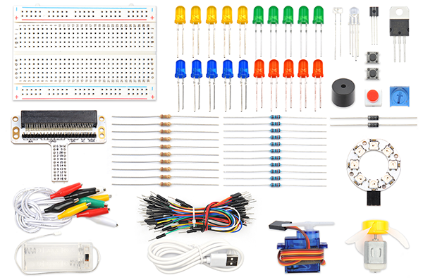
5.3. Components List#
Hardware:#
1 × Pico:ed
1 × USB Cable
1 ×Breadboard Adapter
1 ×Transparent Breadboard - 83 * 55 mm
1 × 10KΩ10K Trimpot
n x Breadborad jumper wire 65pcs pack
5.4. Major Components Introduction#
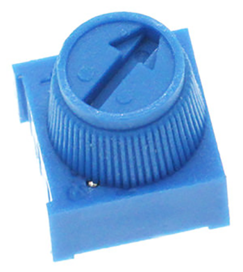
Trimpot#
Trimpot is a kind of adjustable electronic component. It consists of a resistor and a knob or slide system. When adding an external voltage to the two fixed contact points of the resistor, by using a knob or sliding system to change the position of the contact point on the resistor, a voltage with a special relationship to the position of the movable contact is placed on the movable contact. point and two fixed contacts are formed. Most of the time, it works like a voltage divider.
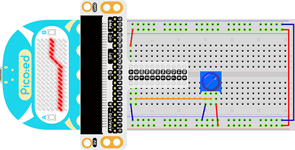
Hardware Connection#
Connect your components according to the picture below:
This is what it looks like after the connection is complete:
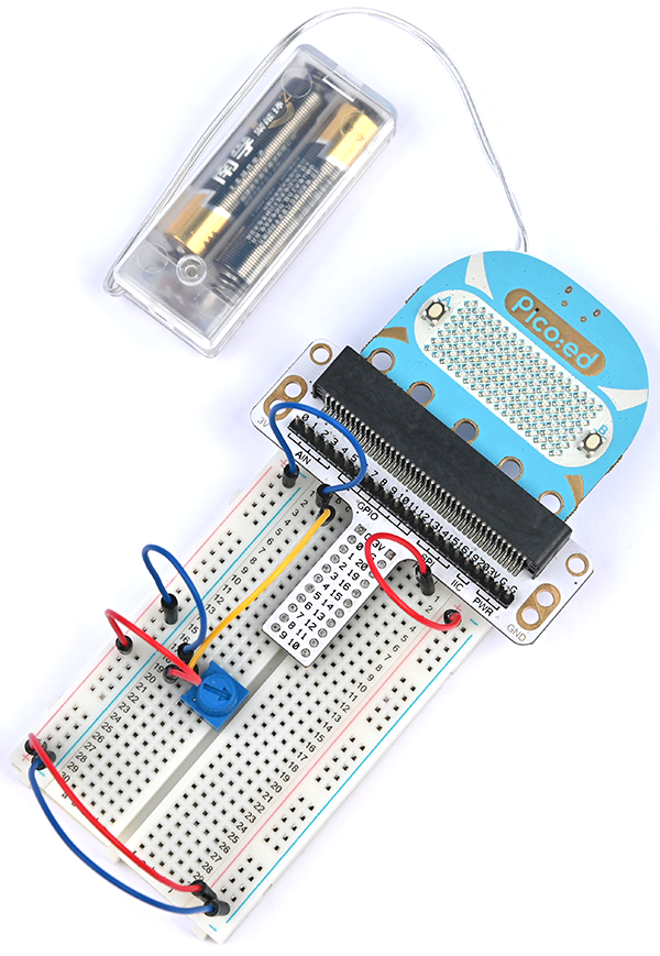
Rotate the button of the Trimpot, then the output voltage will vary between 0V and 3V as the button is rotated.
5.5. Software Programming#
For programming environment preparation, please refer to Introduction to the programming environment
Program as the picture shows:#
# Import the modules that we need
import board
import picoed
import analogio
import time

# Set the pin used by the potentiometer
poten = analogio.AnalogIn(board.P0_A0)

# Initialize the data list, store the value of the potentiometer, so as to set the brightness of the Pico:ed screen LED according to the value of the data list
data = [0, 0, 0, 0, 0, 0, 0, 0, 0, 0, 0, 0, 0, 0, 0, 0, 0]
for i in range(picoed.display.width):
    data[i] = int(poten.value / 9363)


# To cycle converts the value of the potentiometer to the Y coordinate of the LED in the 17th column of the Pico:ed LED screen, and scrolls to the left in turn
while True:

    # pin analog value(0-65535)map to the height of the lattice(0-7)
    data[16] = int(poten.value / 9363)
    for i in range(len(data)):
        picoed.display.pixel(i, data[i] - 1, 0)
        if i != 16:
            data[i] = data[i+1]
        picoed.display.pixel(i, data[i] - 1, 30)
        picoed.display.pixel(16, data[16] - 1, 0)
        time.sleep(0.01)
Details for the code:#
1.Support modules are required by the importer. The board module is a generic container for pin names. could use the board module to specify the pin to use. The digitalio module contains classes that provide access to basic digital IO. The time module contains functions for time settings.
import board
import picoed
import analogio
import time
2.Set the pin used by the Trimpot, we are using P0_A0.
poten = analogio.AnalogIn(board.P0_A0)
If you are using pins other than P0_A0 and P1_A1, you can enter the following code in the shell window below the Thonny editor and press Enter to view the numbers of other pins.
>>> import board
>>> help(board)
object <module 'board'> is of type module
  __name__ -- board
  board_id -- elecfreaks_picoed
  BUZZER_GP0 -- board.BUZZER_GP0
  I2C0_SDA -- board.BUZZER_GP0
  I2C0_SCL -- board.I2C0_SCL
  BUZZER -- board.BUZZER
  BUZZER_GP3 -- board.BUZZER
  P4 -- board.P4
  P5 -- board.P5
  ...
3.Initialize the data list and store the value of the Trimpot to set the brightness of the Pico:ed screen LED according to the value from the data list.
data = [0, 0, 0, 0, 0, 0, 0, 0, 0, 0, 0, 0, 0, 0, 0, 0, 0]
for i in range(picoed.display.width):
    data[i] = int(poten.value / 7000)
4.The loop converts the value of the Trimpot to the Y coordinate of the LED in the 17th column of the LED screen on the Pico:ed, and scrolls to the left in turn.
while True:
    data[16] = int(poten.value / 7000)
    for i in range(len(data)):
        picoed.display.pixel(i, data[i] - 1, 0)
        if i != 16:
            data[i] = data[i+1]
        picoed.display.pixel(i, data[i] - 1, 30)
        picoed.display.pixel(16, data[16] - 1, 0)
        time.sleep(0.01)
5.6. Experimental results#
Turn the Trimpot, and the voltage value will be displayed on the 7*17 LED screen of Pico:ed in the form of a wavy line.
5.7. Exploration#
If we want to use a Trimpot to adjust the brightness of an LED light, how do we design the circuit and program it? Feel free to discuss with us further or leave us a comment.