Lesson 10 Motor
Contents
13. Lesson 10 Motor#
13.1. Introduction#
Motor is a kind of device which can transfer electric energy into kinetic energy according to the law in electromagnetic induction. In this experiment, we are going to use a switch to control the start and stop of a motor.
13.2. Component List#
Hardware:#
1 x micro:bit Board
1 x Micro-B USB Cable
1 x micro:bit Breadboard Adapter
1 x Transparent Breadboard - 83 * 55 mm
1 x 5V Miniature Motors
1 x TIP 120 NPN Transistor
1 x 1N4007 Diodes
1 x 100 Ohm Resistors
n x Breadborad Jumper Wire 65pcs Pack
2 x Alligator Clip Wires
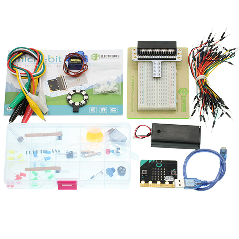
Tips: If you want all components above, you may need Elecfreaks Micro:bit Starter Kit .
13.3. Major Component Introduction#
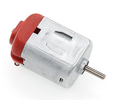
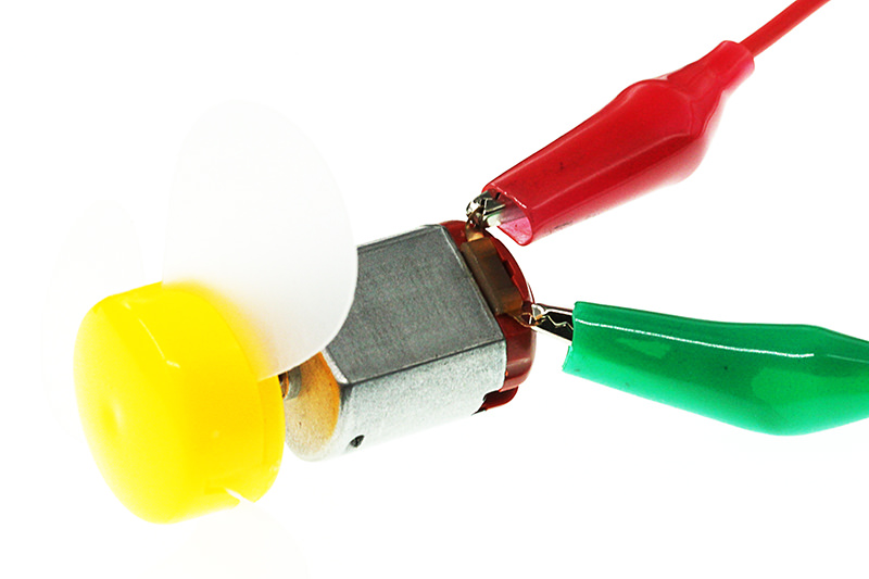
Motor#
Motor is a kind of device that can transfer electric energy into kinetic energy according to the law of electromagnetic induction. Motor has a lot of categories. In our experiment, the motor we use is DC motor. When we supply DC voltage to the two terminals of motor, it will rotate. The higher the voltage, the faster it rotates.
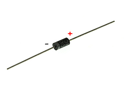
Diodes#
Diode is a kind of component with two polarities: one is for positive and the other is negative. It allows current move from the positive end to the negative end only. We can regard it as an electronic check valve. For common diode, we can judge from the color of tube for its polarity. The terminal with white color is negative polar.
Alligator Clip Wires#
Similar to the usage of jumper cable, alligator clip wire is used when some components are not suitable to use jumper cable for connection.
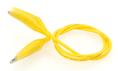
In this experiment, we use alligator clip wire to connect our motor.
13.4. Experimental Procedure#
Hardware Connection#
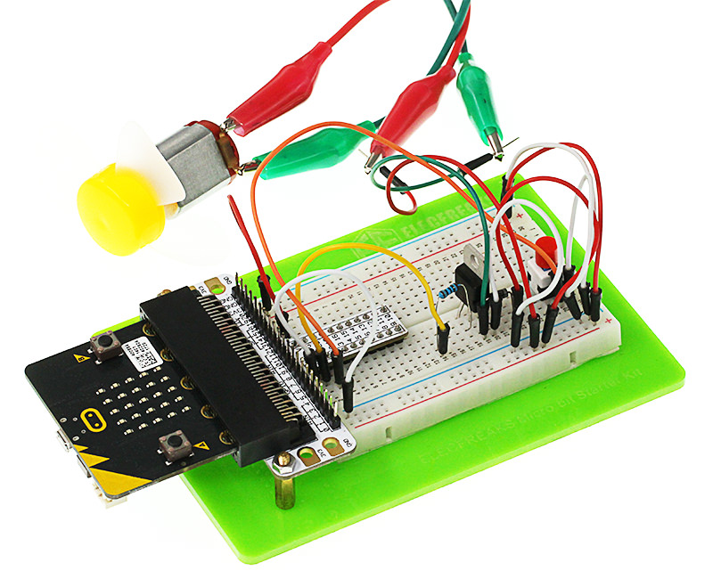
Connect your components according to the picture below:
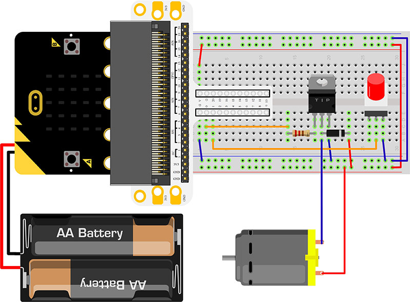
The drive current on micro:bit IO port is too feeble to connect motor directly. At this time, we have to use a triode to amplify the current of IO port. The circuit diagram of using triode to amplify current on IO port is very similar to the circuit diagram of our last chapter “micro:bit Experiment 09:Buzzer —— Elecfreaks mirco: bit Starter Kit Course”. The only difference is the motor has two diodes on its both terminals. And the diode in this circuit is called Freewheel Diode.
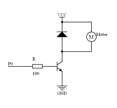
Within the motor, there has a coil. When current flow passes through the coil, it will produce induced electromotive force on the both terminals. When current disappears, the induced electromotive force will generate backward voltage to the components in the circuit. It might damage these components. Freewheel diode connects the two terminals of the coil in anti-parallel. When we cut off the power supply of the inductance coil, the induced electromotive force will not disappear immediately. And the residual force will release by diode. This is a typical design of protection.
Below is the partial circuit diagram of the usage of triode in amplifying the IO port current:
You would see as below after you finish the connection:
Software Programming#
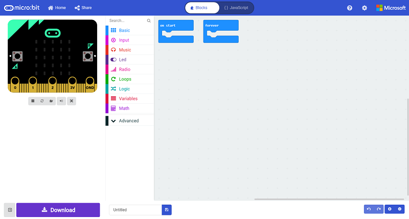
Click to open Microsoft Makecode, write the following code in the editor.(https://makecode.microbit.org/)
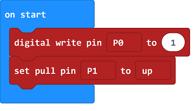
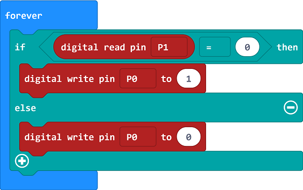
Program as the picture shows:#
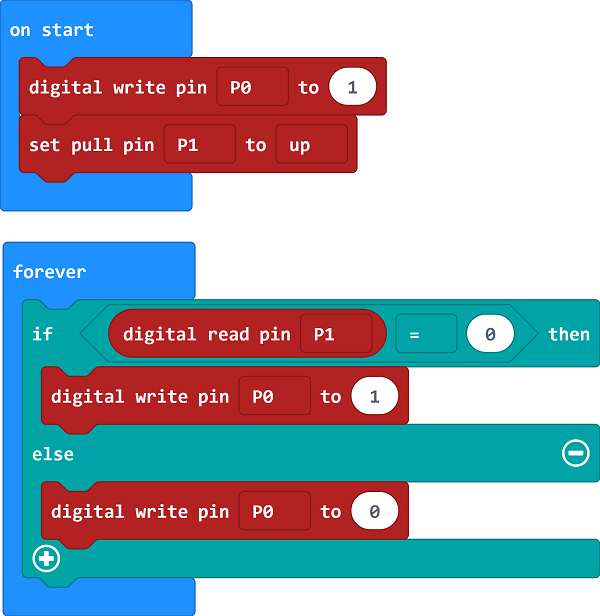
Details for the code:#
1.Digital write pin P0 to 1 and set the P0 port in a high level to recognize the signal of the button normally.
2.When the button is pressed, set P0 to 1; while released, set it to 0.
Reference#
Links:https://makecode.microbit.org/_CAUDezEJrVtc
You can also download the links directly:
13.5. Result#
Press down the button, the motor starts rotating. Press again, it will stop moving. Attention: The voltage of micro:bit power source is low. It is 3V only. Press down the button, the motor may not start. If this happens, please stir the fan blade of the motor so that it can move properly.
13.6. Exploration#
If we want to use a potentiometer to control the motor speed, then how to design circuit and program.