Lesson 03 Trimpot
Contents
6. Lesson 03 Trimpot#

6.1. Introduction:#
Trimpot (or potentiometer) is a kind of common pressure adjustment components. In the following experiment, we are going to read output voltage on trimpot and display it on the micro:bit 5*5 LED screen with bar graph.
6.2. Components List:#
Hardware:#
1 x Micro:bit Board
1 x Micro-B USB Cable
1 x Microbit Breadboard Adapter
1 x Transparent Breadboard - 83 * 55 mm
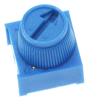
1 x 10K Trimpot
n x Breadborad jumper wire 65pcs pack
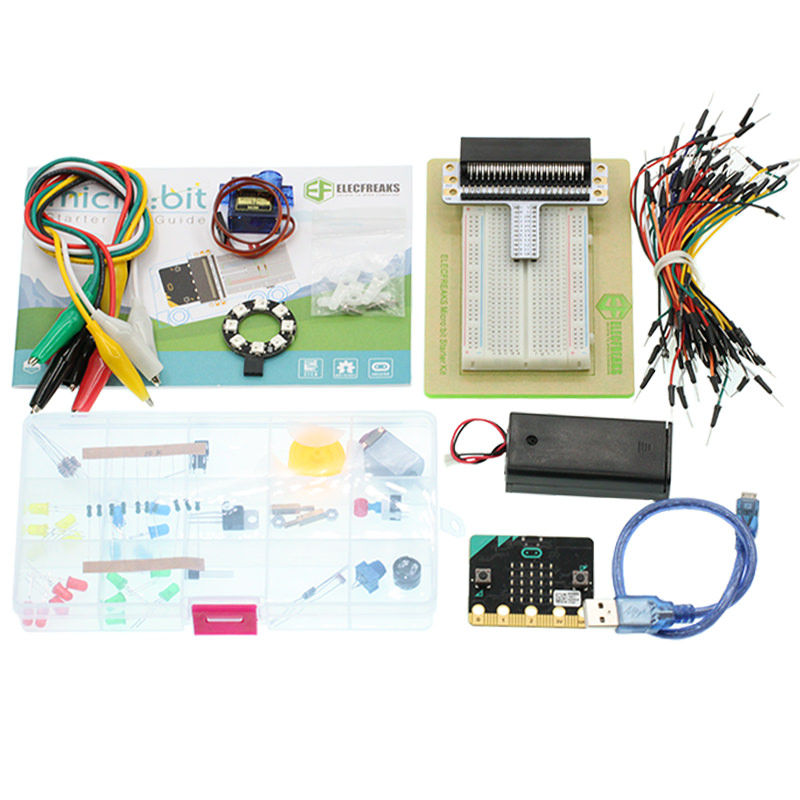
Tips: If you want to buy all components above, you may need Elecfreaks Micro:bit Starter Kit .
6.3. Major Components Introduction#
Trimpot#
Trimpot is a kind of adjustable electronic components. It contains a resistor and a rotary or sliding system. When add an outer voltage on the two fixed contact spots of the resistor, the contact spot of the resistor can be changed by the rotary or the sliding system, a voltage with certain relationship with the place of movable contact spot is formed between movable contact spot and two fixed contact spots. Most of the time, it works as a voltage divider.
6.4. Experimental Procedure#
Hardware Connection#
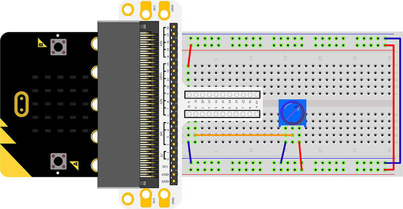
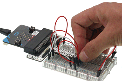
Connect your components according to the picture below:
1.Connect the P0 port of the breadboard adapter with the S port of the Trimpot.
2.Connect the other two ports with the GND and 3V power supply ports.
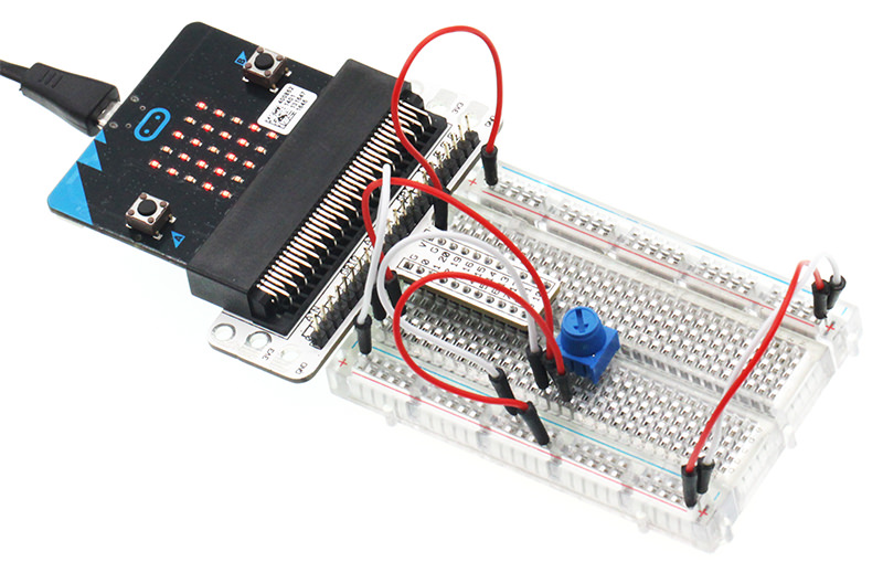
You would see as below after you finish the connection:
Software Programming#
Click to open Microsoft Makecode, write the following code in the editor.
Program as the picture shows:#
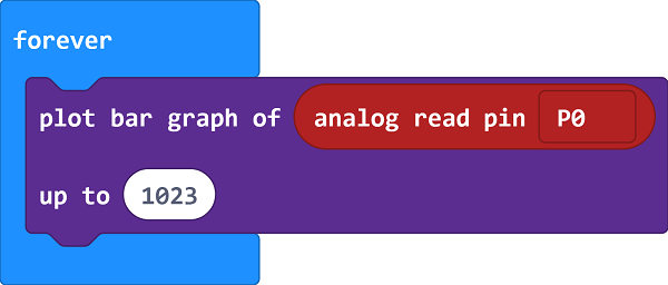
Details for the code:#
Analog read the signal(0~1023) from P0 port and show it on the micro:bit in the form of bar graph.
Reference#
Links:https://makecode.microbit.org/_A2a4C65woMoc
You can also download the links directly below:
6.5. Result#
Rotate the Trimpot button, voltage value will be displayed on micro:bit in the form of bar graph. When voltage read is “0”, the LED screen display a pixel spot only. While the voltage becomes 3.3V, LED screen will be fully illuminated.
6.6. Exploration#
If we want to use Trimpot to adjust the brightness of a LED, how can we design the circuit and program?