case 04 trimpot
Contents
7. case 04 trimpot#
7.1. Introduction#
The trimpot is a common pressure regulation component. In this case, we are going to read output voltage of the trimpot and show the voltage with a bar graph in 5*5 LED allay of micro:bit.
7.2. Products Link#
7.3. Hardware Connect#
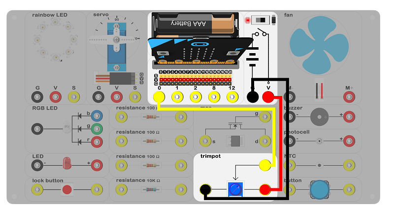 Connect circuit as above picture and put 2 AAA batteries to the batteries pack.
7.4. Principles of Circuits#
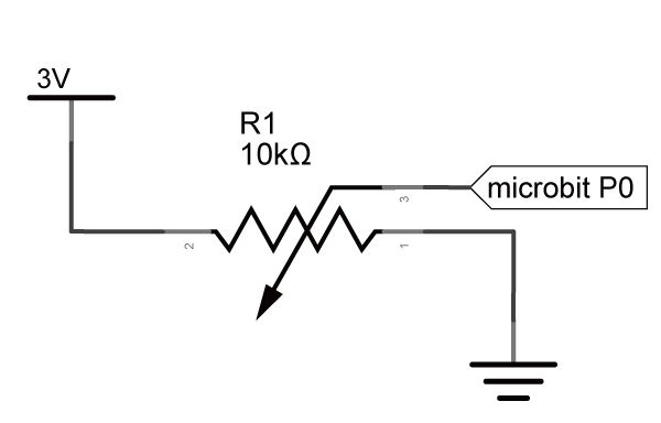
The GND of slot on micro:bit is into innards of batteries’ GND to generate current loop.
7.5. Introduction of Components#
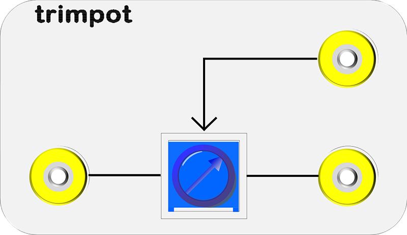
Trimpot#
The trimpot is a pressure regulation component which included a resistance and a slide system. The resistance measured varies based on the movement of a knob or slider between the middle terminal and outer terminals. There is a 10KΩ trimpot on the experiment box. When it turns left, it will be 0Ω; when it turns right, it will be 10KΩ.
7.6. Software#
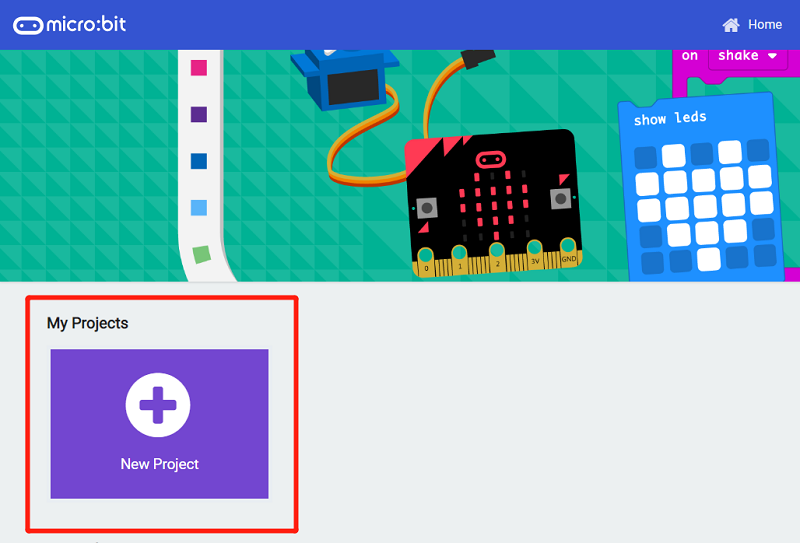
Step 1#
Click makecode https://makecode.microbit.org/#。
Click on “New Project” and set a new Project.
Step 2#

Snap plot bar graph into the forever to show a bar graph.(A bar graph is a kind of table which can show number by diffrent lengths.)
“analog read pin” is to read a signal of a pin.(0~1023)
Program#
Program link:https://makecode.microbit.org/_VewWgwe8HVT1
You also could directly download program by visiting website as below:
7.7. Result#
Rotate the trimpot, the height of the bar graph will change.
7.8. think#
Is the trimpot could be a fixed resistance?