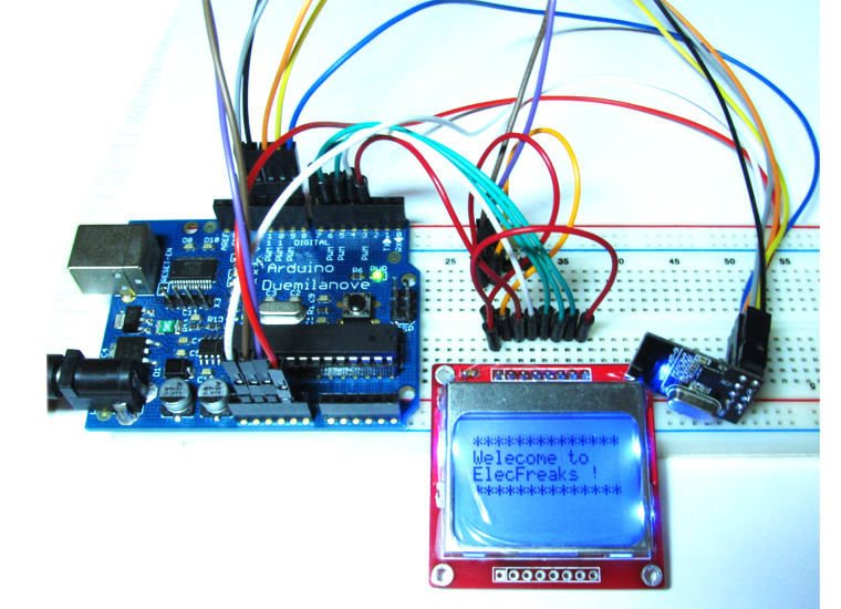
The Easy Radio de A7125
January 4, 2019
Communication between Android and Arduino with Bluetooth(1)
January 4, 2019For the easy radio A7125, there is a reference code generator to give the reference sample demo. You just through change or select the parameters from generator, that can be applied to the user’s system, allowing users to quickly understand and master the basic operation of the A7125. It also easy to use, but the generator current just support FIFO Mode sample demo not support Direct Mode. Get Reference Code Generator here.
1. Radio Channel setting: A7125 support 2400 ~ 2483.5 MHz ISM band, 1 corresponds to 0.5 MHz, 100 corresponds to 50MHz,so the Frequency = 2400.0 + 50MHz = 2450.0MHz, the setting range is 0~166 integer.
2. RF Crystal: Specification for selecting appropriate crystal in A7125 application is given in the following table. Customers can adjust frequency by tuning the external capacitors at A7125 XI and XO pins. But there are A7125 we just provided 16MHz crystal.
3. Data Rate: A7125 has two rate to you selection. 2Mbps and 1Mbps.
4. TX power: Users can get different Tx power by setting TBG (Tx Buffer Gain) and PAC (PA Current) in register [2Dh] as the tables below. The default setting of register [2Dh] is 0x2F. The power variation is about ±2dB between modules.
5. RF ID: Master and Slave must has same ID for communication. The package as below:
6. Sample code mode: FIFO mode and FIFO with ACK, and you can setting ACK and TX byte length, sleep time, delay time and waiting time.
7. Build Reference Code: Check the button and start generate demo code.
8. Select directory
9. SPI mode: There are 3 wires and 4 wires, 3wires mode SDIO has ability to both read and write data, 4 wires mode SIDIO just send data and GPIO2 read data from A7125 to IDE.
10. File save location
11. More information others Ok, if you check the Build buttion, and there will generate three files: define.h, A7125reg.h, main.c. The define.h is define the variable type, A7125reg.h define register and strobe comment, main.c is the main code. About the sample demo, you should change it for different microprocessor. Define.h:
[cce_cpp]
#define Sint8  signed   char
#define Uint8  unsigned char
#define Uint16 unsigned int
#define Uint32 unsigned long
[/cce_cpp]
Delay function: there is a 1us demo function and 100ms demo funtion for reference, maybe you should modifid for other dev platform.
[cce_cpp]
//!!!!!!!!!!!!!!!!!!!!!!!!!!!!!!!!!!!!!!!!!!!!!!!!!!!!!!!!!!!!!!!!!!//
//                      DELAY 1MS FUNCTION                          //
//           USER NEED CHANGE THIS FUNCTION TO FIT SYSTEM.          //
//!!!!!!!!!!!!!!!!!!!!!!!!!!!!!!!!!!!!!!!!!!!!!!!!!!!!!!!!!!!!!!!!!!//
void Delay1ms(Uint8 n)
{
 Uint8 i, j;
 while(n--)
 {
  for(j = 0; j < 6; j ++)
  {
   for(i = 0; i < 235; i ++)
   {
     _nop_();
     _nop_();
     _nop_();
     _nop_();
   }
  }
 }
}
[/cce_cpp]
[cce_cpp]
//!!!!!!!!!!!!!!!!!!!!!!!!!!!!!!!!!!!!!!!!!!!!!!!!!!!!!!!!!!!!!!!!!!//
//                      DELAY 100US FUNCTION                        //
//           USER NEED CHANGE THIS FUNCTION TO FIT SYSTEM.          //
//!!!!!!!!!!!!!!!!!!!!!!!!!!!!!!!!!!!!!!!!!!!!!!!!!!!!!!!!!!!!!!!!!!//
void Delay100us_WTR(Uint8 n)
{
  Uint8 i;
  while(n--)
  {
    for(i = 0; i < 100; i ++)
    {
       if ( RF_WTR == 0 )
          return;
       _nop_();
       _nop_();
       _nop_();
    }
  }
}
[/cce_cpp]


