🐰Happy Easter Day🐰Shop now with up to 30% off sitewide.
Menu


Introduction
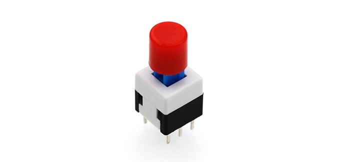
Self-lock switch is a kind of common button switch. When we press its button for the first time, the switch is connected and remains that status, which is called “self-lock”. When we press the button for the second time, the switch is disconnected. At the same time, the button will bounce back to its initial place. In this experiment, we are going to use self-lock switch to control LED light.
Component List
Hardware:
1 x Micro:bit Board
1 x Micro-B USB Cable
1 x Microbit Breadboard Adapter
1 x Transparent Breadboard – 83 * 55 mm
1 x Self-lock Switch
1 x LED
1 x 100 Ohm Resistors
1 x Breadborad jumper wire 65pcs pack
Tips: If you want all components above, you may need Elecfreaks Micro:bit Starter Kit.
Software:
Microsoft Makecode online editor
Major Components Introduction
Self-lock Switch
Self-lock switch normally means switch with built-in mechanical lock function. Press down the switch and then release, it will not fully bounce up because it is locked. You have to press it again, then it will be unlocked and fully bounce up. This is the so-called Self-lock Switch. It is widely used to earlier televisions and monitors with function of directly completely power off.

Note: This kind of self-lock switch contains two groups of double-throw switch. In this experiment, we use a group only. So we cut down the common footer of a group.
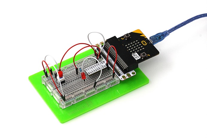
Hardware Connection:
Please complete hardware connection according to the picture below. 

Programming
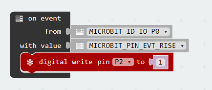
Please open Microsoft Makecode, write your code in the edit area. I would like to suggest you to program by yourself first. Of course, you can see the whole program directly in the link below. Just click Edit on the top right corner of the interface to start edit your program. Once you completed edit, click Downloadin the bottom right corner of the interface to download your code directly into Micro:bit.
set events Configure the type of events emitted by a given pin. on events Raise an event in the event bus.

In this case, w designed 2 events: P0 voltage rise and fall. Every time we press down the switch, voltage in P0 port will change for once. When voltage start shifting from 0V to 3.3V, we call it ” Rise”. When voltage start shifting from 3.3V to 0V, we call it ” Fall”.

Experiment Result
Press down self-lock switch, LED turned on; press again, LED turned off.
Question
Usually stair light use double-throw switch to realize this function. We can turn on the light of upstairs and turn off the light of downstairs. Vice versa. Suppose if we want to use 2 self-lock switch to realize stair light function, then how to design circuit and program? We look forward to your comments or further discussion with us.
Relative Readings
Start Your Micro:bit Programming Trip Micro:bit Experiment 01: LED Scroller —— Elecfreaks Mirco: bit Starter Kit Course Micro:bit Experiment 02: Button —— Elecfreaks Mirco: bit Starter Kit Course Micro:bit Experiment 03: Trimpot —— Elecfreaks Mirco: bit Starter Kit Course Micro:bit Experiment 04: Photocell — Elecfreaks Mirco: bit Starter Kit Course Micro:bit Experiment 05: RGB LED —— Elecfreaks Mirco: bit Starter Kit Course
Stay up-to-date with our latest promotions,discounts,sales,and special offers.