Bluetooth Modem Video Tutorials
January 11, 2019
Tips for Choosing the Best Bluetooth Shield for Arduino Project
January 11, 2019Hi, we persistently spare no efforts updating our tutorial to provide better technical support and unsurprisingly, tremendous customers finally get their problems resolved through download our user guide and watching video. we are really happy to see the beginners grow and develop in electronics DIY. Currently we release one quickly-user-guide and video for Bluetooth Bee HC-05 and Bluetooth Bee HC-06. To some extent, this user guide is similar to the previous Bluetooth Shield, anyway, have a look at it.
Bluetooth Bee (HC-05/HC-06) Introduction
Bluetooth Bee is a simple breakout board for the Bluetooth Module, pin distance as 2.0mm, compatible with all XBee interface and XBee module, designed for transparent wireless serial connection setup. Bluetooth Bee can be configured to Master, Slave or Loopback three different modes (HC-06 not for Master Mode), and it will connect to or be connected by other devices that support SPP protocol per configuration, and it is a suitable substitute for most applications. This is a fully qualified Bluetooth V2.0+EDR (Enhanced Data Rate) 3Mbps modulation with complete 2.4GHz radio transceiver. It uses CSR Bluecore4-external single chip Bluetooth system with CMOS technology and with AFH (Adaptive Frequency Hopping).
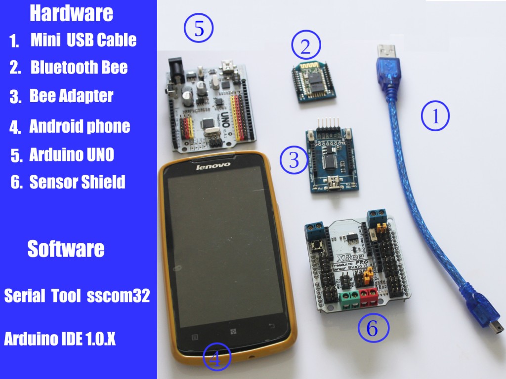
Hardware and Software Preparation
Part 1 Communication Between Bluetooth Bee and Bee Adapter
1. Set the Bee Adapter switch in H port to enter AT Mode. Make sure Bluetooth Bee LED blink slowly in AT Mode. Assemble the Bee Adapter and Bluetooth Bee, then connect it to PC.
2. Open Serial Tool sscom32 and set the BaudRate as 38400. Type AT, and it would respond OK. With Bee Adapter, you can achieve AT Command control not need of programming code.
Part 2 Communication Between Arduino and Bluetooth Bee with Sensor Shield
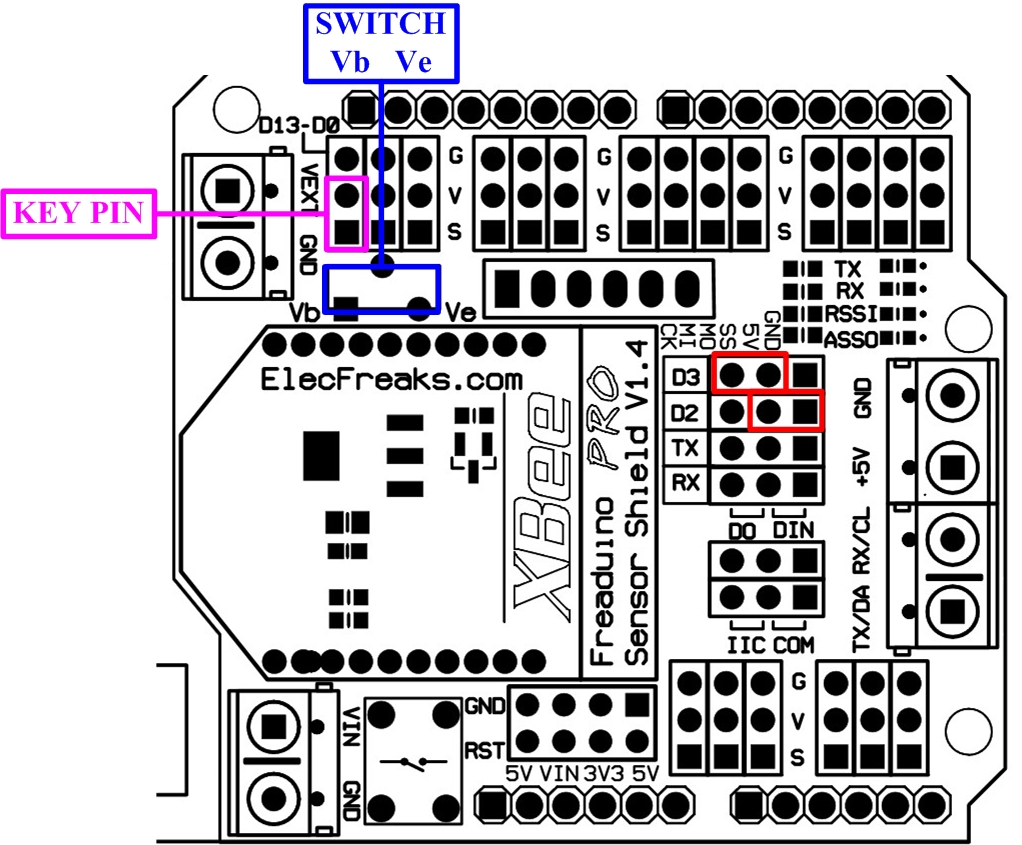
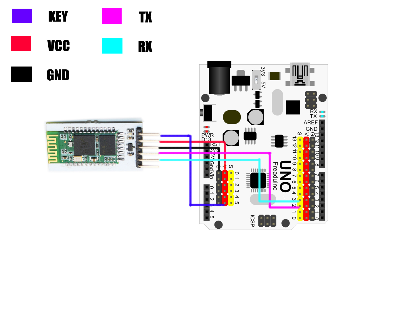
1. For Sensor Shield, make sure the short cap on KEY PIN to enter AT Mode.
2. Set the Sensor Shield switch in Vb port to power supply from the board not from external.
3. Put short caps on D2/D3 to connect to Software Serial Tool.
4. Assemble the Arduino UNO, Sensor Shield and Bluetooth Bee, making sure the Bluetooth Bee LED blink slowly in AT Mode.
Step 1. Achieve Manually AT Command Control
1. Open the Arduino IDE 1.0.X, and copy the code from Elecfreaks wiki to it.
2. Import library of SoftwareSerial, because library of NewSoftSerial is just suitable of edition before ArduinoIDE 1.0, such as IDE0022, IDE0023.
3. Delete the library of NewSoftSerial and modify the NewSoftSerial into SoftwareSerial.
4. Download TimerOne from http://code.google.com/p/arduino-timerone/downloads/list
5. Compiling sketch until Done compiling appears
6. Upload code until Done uploading appears
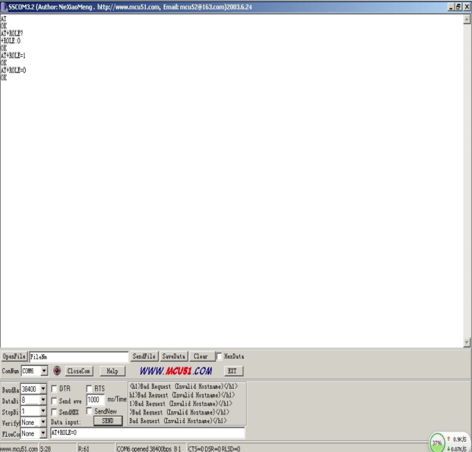
7. Open sscom32 and set BaudRate as 38400
8. Manually input AT and it would respond OK
9. Input AT+ROLE? And it would respond +ROLE=0, therefore, We default the Bluetooth Bee as SLAVE Mode
10.Input AT+ROLE=1, we can set it as Master Mode (just for HC-05, not HC-06) 11.Input AT+ROLE=0, we can set it back as SLAVE Mode
Step 2. Achieve Automatically AT Command Control
1.Modify the code (Remove // before Timer1)and then upload it again in Arduino IDE 1.0.X
2.It can automatically respond OK for AT Command
Part 3.Communication Between Android and Arduino with Bluetooth
1.Take off the short cap from Sensor Shield KEY PIN to enter Communication Mode. In Communication Mode, make sure the Bluetooth Bee LED blink quickly. If necessary, re-plug the USB Cable.
2. Modify the code (add // before Timer1, especially replace the BaudRate from 38400 to 9600 ), and then upload the code again.
Step 1. Android Installation
1. Download APP for EF _BluetoothBeeV1.1 from http://elecfreaks.com/store/download/datasheet/Bluetooth/EF_BluetoothBeeV1.1.zip
2. Install the APK file to your Android phone.
Step 2. Android Communication
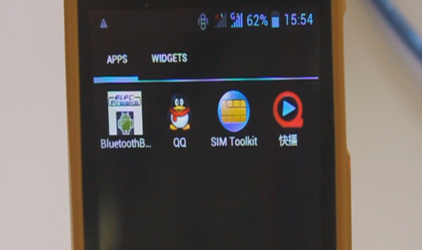
1. Click the icon of ElecFreaks BluetoothBee as above and then open Bluetooth.
2. Click As Client and start scanning
3. When it scan out HC-05, click HC-05.
4. Type the Bluetooth pairing request 1234.
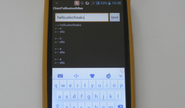
5. Input hello,elecfreaks in mobile, and the PC would display hello,elecfreaks from mobile. (For sscom32, remember to set the BaudRate as 9600.)
6. Input hello from PC, mobile would also respond hello.
Q&A
If you use Arduino Mega1280/2560 or Freaduino ADK there are some difference. Please note the NewSoftSerial library about Mega2560 explanation in SoftwareSerial.cpp :
[cce]
// Specifically for the Arduino Mega 2560 (or 1280 on the original Arduino Mega)
// majority of the pins are NOT PCINTs, SO BE WARNED (i.e. you cannot use them as receive pins)
// Only pins available for RECEIVE (TRANSMIT can be on any pin):
// (I've deliberately left out pin mapping to the Hardware USARTs - seems senseless to me)
// Pins: 10, 11, 12, 13, 50, 51, 52, 53, 62, 63, 64, 65, 66, 67, 68, 69
[/cce]
That means the library do not support D0-D7 as receiving pins, and you just could use pins:10, 11, 12, 13, 50, 51, 52, 53, 62, 63, 64, 65, 66, 67, 68, 69 for receiving. So there are two way to resolve it, but they all need external jumper wires.
First method:
Change the define of rxPin and txPin. Jumper wires connect to DOUT-D10, DIN-D11.
[cce]
#define rxPin 10
#define txPin 11
[/cce]


