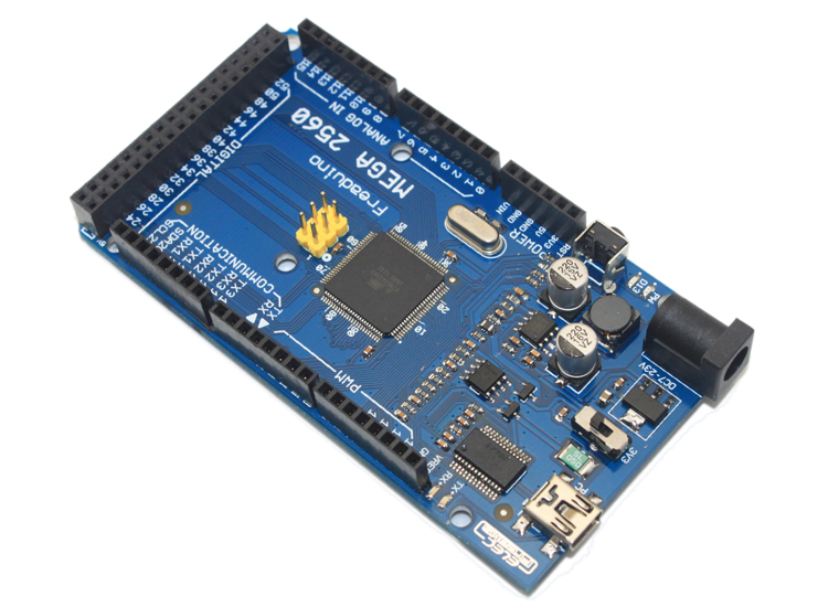
Freaduino MEGA2560 v1.2 (100% Arduino compatible)
January 12, 2019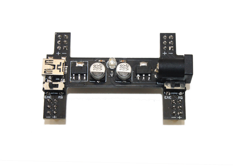
Black Wings (3.3v/5v Power Module Breadboard Adapter)
January 12, 2019The DDS module is base on AD9850 which is provided by ADI Company and common used in many DDS module.The chip provide 0-40MHz measurement capability. Here we will show you how to control AD9850 module by Arduino, and then show the output wave by Lxardoscope, which is an Arduino based oscilloscope for Linux, using the Xforms library. You can get more detailed how to use it from our other post Linux+Arduino open oscilloscope – Lxardoscope. The DDS module of AD9850/AD9851 has two data transfer modes :
Serial mode and Parallel mode.
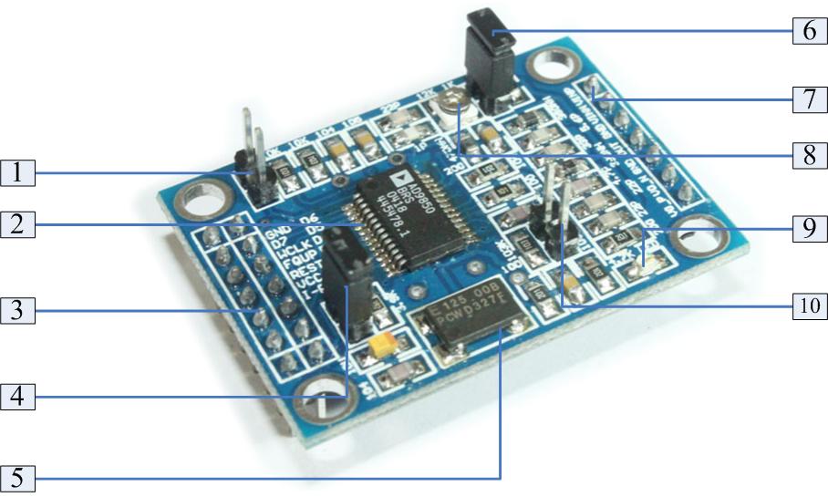
You can select one of them by Label 1 as below figure.
More detailed about the DDS pin define from our Wiki. Here I just show you how to quick control AD9850 and show wave on Lxardoscope.
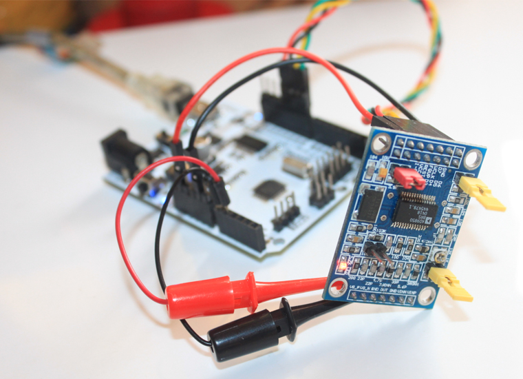
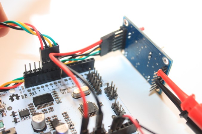
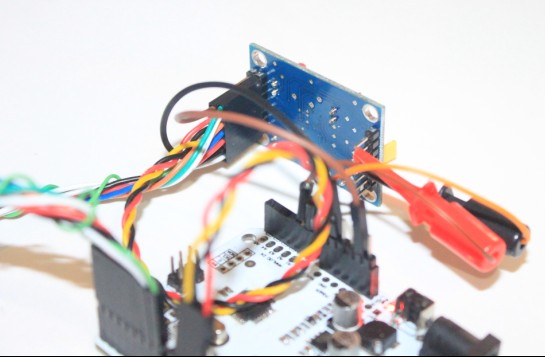
First of all, of course, you need one Arduino boards and one DDS module, and some of jumper wires and at least one of test hook. If you don’t have, you can get them in our store in a very low cost. If you use a standard Arduino board, you’d better use the Arduino board’s 3.3V pin(VDD3V3???to provide power. Of course you can use 5V which the DDS module of AD9850 max support power supply. The Serial mode of demo pins to Arduino as below:
GND–GND, VCC – 3.3V, BitData(D7)- D8, CLK – D9, FQUP – D10, REST – D11 Test Hook Red – Square Wave 1, Test Hook Black – Sine Wave 1(with 70MHz Low-pass filter)
Download our library for DDS AD9850 Serial mode, run the example demo of LXARDOSCOPE. The demo code as below:
[cce_cpp]
/*********************************************************************
**  Device: AD9850/9851                                             **
**  File:   EF_AD9850.cpp	v1.2			            **
**								    **
**  Created by ElecFreaks Robi.W /28 Oct 2011                       **
**                                                                  **
**  Description:                                                    **
**  This file is a sample code for your reference.About AD9850/9851 **
**  module use on Arduino with serial mode. And then show the       **
**  square wave and sine wave by LXARDOSCOPE which is an free       **
**  Arduino based oscilloscope Linux, using the Xforms library.     **
**  Note:This library just Serial mode for AD9850                   **
**                                                                  **
**  This demo code is free software; you can redistribute it and/or **
**  modify it under the terms of the GNU Lesser General Public	    **
**  License as published by the Free Software Foundation; either    **
**  version 2.1 of the License, or (at your option)   		    **
**  any later version.						    **
**                                                                  **
**  Copyright (C) 2011 ElecFreaks Corp.                     	    **
**                                                                  **
**  http://www.elecfreaks.com                                       **
*********************************************************************/

#include

//Define for LXARDOSCOPE
int sensorValue = 0;        // value read from the pot
byte lb;
byte hb;

//BitData - D8, CLK - D9, FQUP - D10, REST - D11
EF_AD9850 AD9850(9, 10, 11, 8);

void setup()
{
  AD9850.init();
  AD9850.reset();
  AD9850.wr_serial(0x00, 200); //200Hz
  // initialize serial communications at 115200 bps:
  Serial.begin(115200);
}

void loop(){
  // read A0:
  sensorValue = analogRead(A0);
// shift sample by 3 bits, and select higher byte
  hb=highByte(sensorValue<<3);
// set 3 most significant bits and send out
  Serial.print(hb|224,BYTE);
// select lower byte and clear 3 most significant bits
  lb=(lowByte(sensorValue))&31;
// set bits 5 and 6 and send out
  Serial.print(lb|96,BYTE);
// read A1
  sensorValue = analogRead(A1);
// shift sample by 3 bits, and select higher byte
  hb=highByte(sensorValue<<3);
// set bits 5 and 6 and send out
  Serial.print(hb|96,BYTE);
// select lower byte and clear 3 most significant bits
  lb=(lowByte(sensorValue))&31;
// set bits 5 and 6 and send out
  Serial.print(lb|96,BYTE);
}
[/cce_cpp]
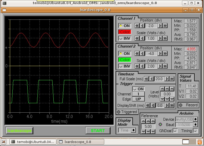
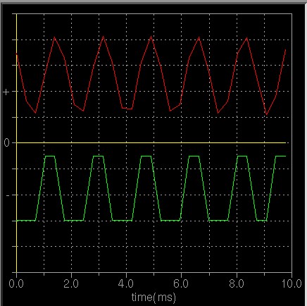
Then connect to you Linux’s Lxardoscope, type ‘ lxardoscope /dev/ttyUSB0 ‘. There will show the square wave and sine wave on lxardoscope menu as before.
Note:
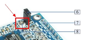
- If you can’t see square wave as figure, please change duty cycle adjustable at label 8 postion.
- lxardoscope just support a 420 Hz sine wave and a 1471Hz square wave from a sound card based generator are displayed. So we demo set 200Hz for test. If setting 600Hz will distortion as below:
- lxardoscope just for verify the DDS module is work well. The data just for you reference.
The Parallel mode of demo pins to Arduino as below:
GND–GND, VCC – 3.3V, BitData(D0-D7) – PORTD(D0-D7), CLK – D9, FQUP – D10, REST – D11 Test Hook Red – Square Wave 1, Test Hook Black – Sine Wave 1(with 70MHz Low-pass filter)
Download our Arduino Parallel mode code for DDS AD9850 Serial mode, run the example demo of LXARDOSCOPE.
[cce] //Define for AD9850 #define REST 11 #define FQUP 10 #define CLK 9 #define BitData_Port PORTD #define BitData_DIR DDRD #define BitData_IN PIND //Define for LXARDOSCOPE int sensorValue = 0; // value read from the pot byte lb; byte hb; void AD9850_Init(){ …… } void AD9850_Reset(){ ….. } void AD9850_WR(unsigned char w0,double frequence){ …… } void setup(){ AD9850_Init(); AD9850_Reset(); AD9850_WR(0x00, 200); //500Hz // initialize serial communications at 115200 bps: Serial.begin(115200); } void loop(){ // read A0: sensorValue = analogRead(A0); // shift sample by 3 bits, and select higher byte hb=highByte(sensorValue<<3); // set 3 most significant bits and send out Serial.print(hb|224,BYTE); // select lower byte and clear 3 most significant bits lb=(lowByte(sensorValue))&31; // set bits 5 and 6 and send out Serial.print(lb|96,BYTE); // read A1 sensorValue = analogRead(A1); // shift sample by 3 bits, and select higher byte hb=highByte(sensorValue<<3); // set bits 5 and 6 and send out Serial.print(hb|96,BYTE); // select lower byte and clear 3 most significant bits lb=(lowByte(sensorValue))&31; // set bits 5 and 6 and send out Serial.print(lb|96,BYTE); } [/cce]
If you have any problem, please feel free to contact us. Any of you suggestion is help.
Download :


